
How mmWave empowers LEO satellite communications: Opportunities and design challenges
Insights
Millimeter-wave (mmWave) technology — particularly Ka-band uplink and K-band downlink — has become the backbone of next-generation low Earth orbit (LEO) satellite communications, enabling the broadband connectivity that terrestrial networks can’t reach, including remote regions, extreme terrains, maritime routes, and disaster-hit areas. As satellite communications (SATCOM) evolve from simple relay stations into fully functional airborne base stations, they now support bidirectional links with ground stations, user terminals, and mobile platforms such as aircraft, fishing vessels, and automobiles — making them a cornerstone of both national communication resilience and the emerging new space economy.
Satellite connectivity is a critical enabler of reliable communications wherever deploying terrestrial infrastructure is economically impractical, providing mission-critical links for:
- Underdeveloped regions: bridging the digital divide in underserved areas
- Extreme terrains: ensuring uninterrupted coverage across mountains and deserts
- Maritime operations: sustaining reliable networks for offshore fishing fleets and commercial vessels
Since the Russia–Ukraine war, satellite communications have proven their ability to rapidly restore connectivity after terrestrial infrastructure is disrupted or destroyed, underscoring their strategic value for maintaining high-quality communications. As a result, SATCOM has become a cornerstone of national communication resilience and defense strategy.
A satellite communication system generally consists of three major components:
- Satellite communication payloads
- Ground stations (including ground station modems)
- User terminals
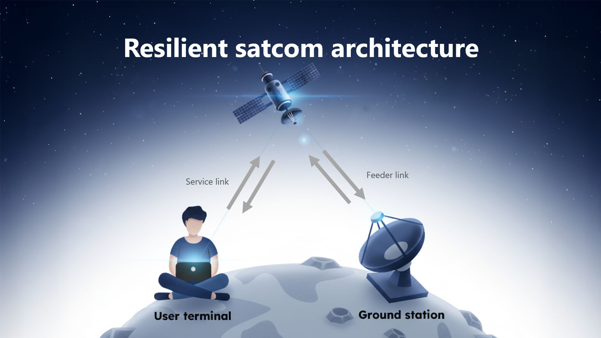
Ground stations connect to terrestrial networks and exchange information with end-user terminals through satellite links.
LEO satellite communications: Frequency bands and market trends
Satellite systems are typically classified by orbital altitude:
|
Orbit class |
Altitude range |
Propagation delay |
Coverage & market application |
| LEO (Low Earth Orbit) | Below 2,000 km | Low latency | Ideal for broadband; lower deployment cost; requires a dense constellation |
| MEO (Medium Earth Orbit) | 2,000–36,000 km | Medium latency | Moderate coverage; suited to navigation and tracking |
| GEO (Geostationary Orbit) | Above 36,000 km | High latency | Stationary relative to Earth; higher path loss |
Compared with higher-orbit systems, LEO satellites offer lower deployment cost, reduced latency, and a moderate coverage footprint — making them well suited to broadband services, though they require a larger constellation and higher operational cost to maintain full coverage.
For Taiwan and the broader satellite ecosystem, including manufacturers and payload suppliers, this shift represents a substantial market opportunity. As satellite communications gain strategic importance for national resilience and security, countries around the world are accelerating plans for sovereign satellite constellations, further driving demand for payload technologies.
Taiwan is likewise advancing its own national constellation, with a roadmap to deploy more than 60 LEO satellites. The current frequency plan calls for:
- 28 GHz Ka-band for user uplink
- 18 GHz K-band for user downlink
Today, uplink communications between LEO ground stations and satellites are predominantly implemented in Ka-band mmWave, while downlink typically operates in K-band.
YTTEK’s development in mmWave and satellite communications
YTTEK originated from a team established by the Industrial Technology Research Institute (ITRI) in 2014 to develop 5G mmWave small cells. Built on a foundation of wireless communication systems and Software-Defined Radio (SDR), YTTEK has long focused on advancing mmWave technology.
To deliver mission-critical reliability, our core expertise spans:
- mmWave phased-array antennas
- RF front-end design
- Communication algorithms
- FPGA baseband processing
- Network protocol implementation
- System integration
Building on this mmWave foundation, YTTEK has expanded into LEO satellite communications through a collaboration with the Taiwan Space Agency (TASA) on satellite communication payloads and ground station modem development.
In early 2024, YTTEK’s X/Ku-band ground station modem, HyperSDR, successfully received, demodulated, and decoded signals from TASA’s FORMOSAT-5 as well as NASA’s Landsat-8 and Landsat-9 satellites. On the user terminal (UT) side, YTTEK also received strategic investment from AUO in 2022 to jointly develop automotive glass antennas and satellite communication user terminals.
3GPP NTN standards: Opportunities for mmWave phased-array antennas
Satellite communications currently lack a unified international standard. However, 3GPP — the global standards body for mobile communications — is actively developing standards for Non-Terrestrial Networks (NTN). These cover a range of High Altitude Platform Stations (HAPS), including:
- High-altitude balloons
- Unmanned aerial vehicles (UAVs)
- LEO satellites
Among these, satellite communications are widely regarded as one of the most promising infrastructures for next-generation mobile networks. Current 3GPP NTN FR2 development also favors 28 GHz Ka-band uplink and 18 GHz K-band downlink, supporting the broadband, high-speed connectivity needed for multimedia and entertainment services.
Taiwan’s ICT industry — with a complete supply chain spanning antennas, communication modules, and PCB manufacturing, backed by years of accumulated experience — is well positioned to participate in this supply chain. However, because most LEO operators today rely on proprietary standards, and 3GPP NTN standards currently address only IoT applications (with broadband standards still two to three years from maturity), Taiwan’s role currently centers on ground-station components: Electronically Steered Arrays (ESA), satellite antenna Low-Noise Block downconverters (LNB), and PCBs.
Within this landscape, YTTEK’s decade-plus of expertise in mmWave phased-array antennas and wireless communication systems — together with its proven X/Ku-band satellite communication payloads and ground station modems — makes it one of the few Taiwan-based companies with demonstrated design capability across both segments. This positions YTTEK to help build a more complete, self-reliant satellite communication ecosystem in Taiwan.
Design challenges: Link budget limitations and payload mass
Launch cost is driven primarily by payload mass, so miniaturization directly reduces launch expense. Advances in semiconductor manufacturing and precision engineering have accelerated the shift toward compact satellites, with CubeSat — a standardized cube-form platform — emerging as an effective way to lower development costs.
Satellite links spanning hundreds or thousands of kilometers require careful link budget optimization, expressed as:
TX Power = Path Loss + RX Antenna Gain + RX Power
Because satellite payloads are constrained by power and size, transmission power must be minimized to reduce energy consumption. Communication performance is instead achieved through a combination of higher ground station transmit power and greater receive antenna gain — which drives the need for large-scale antenna arrays capable of compensating for long transmission distances and severe propagation loss.
For user terminals, antenna array size varies with service requirements: text messaging, voice, and broadband multimedia each demand different levels of bandwidth and performance, which in turn dictate different gain requirements and array sizes.
Example: Link budget in a practical LEO deployment
Consider the downlink budget of Eutelsat OneWeb, whose satellites operate at an altitude of approximately 1,200 km:
- Center frequency: 12 GHz
- Satellite transmit power: 36 dBWi
- Elevation angle: 45°
- Slant range: approximately 1,580 km
Under these assumptions, path loss reaches approximately 178 dB. Practical deployments must also account for additional losses, including pointing loss, rain fade, and atmospheric loss.
As a result, even within a relatively narrow 10 MHz bandwidth, maintaining basic modulation performance may require phased-array architectures with at least 512 elements — and potentially more, depending on service targets and environmental conditions.
As operating frequency rises, wider bandwidth becomes achievable, but propagation loss increases as well — pushing demand toward ever-larger electronically steered arrays. Architectures with 1,024 or even 2,048 elements are becoming increasingly relevant for future broadband LEO systems. This challenge is especially pronounced in mmWave satellite communications, where RF efficiency, thermal dissipation, packaging integration, calibration complexity, and manufacturing scalability all become significantly harder to manage.
Solving thermal management and PAE challenges in massive phased arrays
Massive phased-array beamforming compensates for severe propagation loss at higher frequencies and longer distances. As element count increases, beamwidth (Half Power Beam Width, HPBW) narrows and array gain improves.
However, as operating frequency rises, the Power Added Efficiency (PAE) of the power amplifier (PA) tends to fall. Lower PAE means only a small fraction of DC power is converted into transmitted signal — the rest is dissipated as heat, creating a serious thermal management challenge.
Integration is another key challenge at scale. A 512-element array built on conventional high-frequency PCB material, for instance, can be implemented either as a single monolithic substrate or as modular sub-arrays — such as 4- or 16-element tiles — combined into the full array. From a manufacturing yield standpoint, the modular approach is generally preferable, since it prevents a defect in one or a few elements from scrapping the entire array.
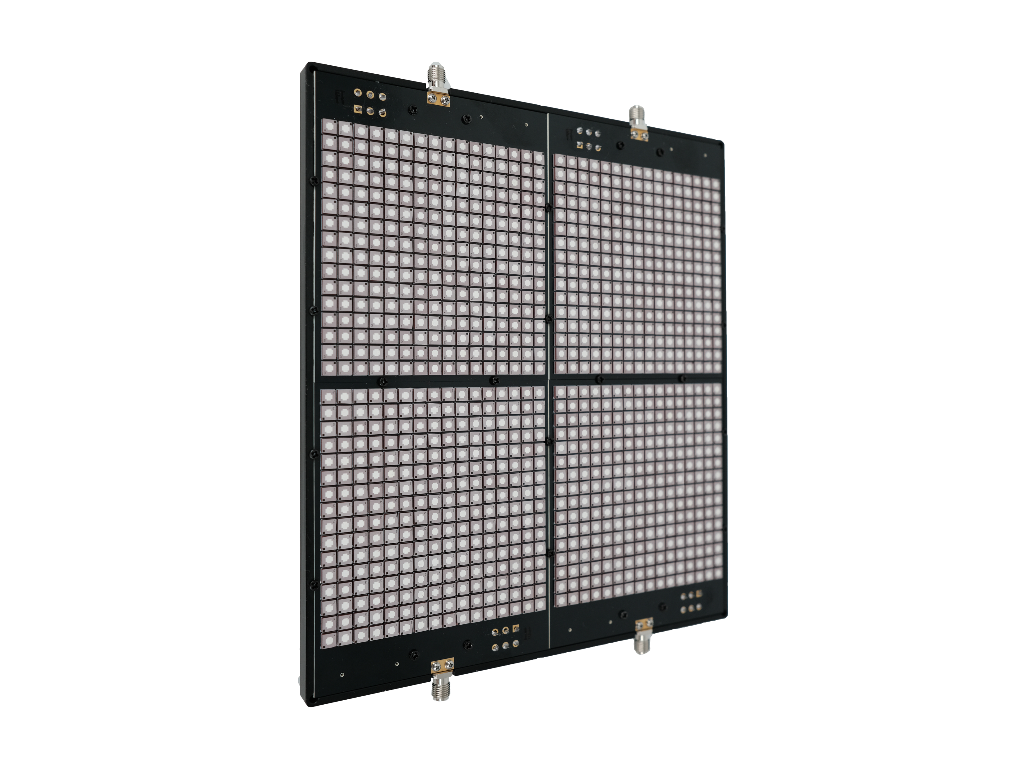
YTTEK’s 1,024-element, 28 GHz large-scale mmWave phased-array antenna illustrates this approach: its antenna elements use Low Temperature Co-fired Ceramic (LTCC) technology, while a multilayer motherboard — built with conventional PCB materials and sized to the array’s scale and control requirements — ties the system together. This architecture significantly reduces mutual coupling between elements while substantially lowering the overall cost of the array.
Conclusion: The future of mmWave LEO satellite networks
Recent developments in global LEO satellite communications mark the beginning of a transformative era for wireless systems, satellite infrastructure, and resilient network architecture. Satellite internet has already become part of national strategic infrastructure initiatives worldwide.
Small satellite platforms like CubeSat are lowering the barrier to entry — but at the same time, Taiwan must keep strengthening its indigenous capabilities in satellite communication technology, particularly in Ka-band phased-array antennas, satellite communication payloads, ground station systems, and user terminal development.
“As the industry evolves toward integrated land-air-sea-space connectivity, countries and companies capable of developing autonomous satellite communication systems using mmWave and SDR technologies will gain long-term strategic and commercial advantages in the New Space era,” said Jiangson Chen, CEO of YTTEK.
Ready to elevate your space mission? Discover how YTTEK’s mission-proven, end-to-end SATCOM solutions—from satellite communication payloads to satellite ground station modems—can accelerate your critical satellite operations. Contact our experts today for detailed specifications and a customized solution.
Learn more about HyperSDR Satellite Ground Station Modem >>
Learn more about SDRspace Satellite Communication Payload >>
Frequently asked questions
Why is mmWave important for LEO satellite communication?
mmWave enables wider bandwidth and higher data throughput than traditional satellite frequency bands, making it essential for broadband LEO satellite communication services. Frequency bands such as Ka-band support high-speed connectivity for applications including satellite internet, mobility services, and future 6G NTN networks.
What is the biggest technical bottleneck when applying mmWave frequencies to satellite communications?
The primary challenge is path loss. In the OneWeb downlink example discussed above—a satellite at 1,200 km altitude, transmitting at 36 dBWi with a center frequency of 12 GHz and a 45° elevation angle (corresponding to a slant range of approximately 1,580 km)—the path loss alone reaches approximately 178 dB, before accounting for additional losses such as pointing loss, rain fade, and atmospheric absorption. As operating frequency increases toward Ka-band, this path loss grows further, requiring systems to rely on large-scale phased-array antennas—512, 1,024, or even 2,048 elements—to generate sufficient beamforming gain. On top of that, power amplifiers exhibit lower Power Added Efficiency (PAE) at higher frequencies, meaning a greater share of DC power is converted to heat rather than RF energy. Thermal dissipation therefore becomes one of the most demanding aspects of mmWave antenna module design.
What are the advantages of a modular antenna architecture over a monolithic design?
With a monolithic large-scale array — say, 512 elements fabricated on a single substrate — any localized defect introduced during PCB manufacturing or SMT assembly can render the entire board unusable, resulting in significant material and cost losses. A modular approach, building the array from smaller sub-units such as 4- or 16-element tiles, allows for independent testing, selective replacement, and tighter yield control at each stage of production. When combined with a hybrid material strategy — LTCC ceramic for the antenna modules and standard PCB for the motherboard — this architecture simultaneously addresses RF coupling, manufacturing yield, and total production cost.
What solutions does YTTEK provide for the satellite communication ecosystem?
YTTEK provides end-to-end SATCOM solutions spanning both ground and space segments, including the mission-proven HyperSDR X/Ku-band ground station modem and SDRSpace X/Ku-band satellite communication payloads.